
How BIM Simplifies Fabrication Drawings for Fabricators and Contractors
The broken design-to-fabrication process, where design models get transferred to fabricators to reinterpret and draw everything manually, causes rework, delays, and additional costs, negatively affecting the project profitability right from the start. This blog post outlines a step-by-step BIM workflow that generates accurate fabrication drawings and shop packages of structures, MEP, and prefabrications, making sure what goes to the shop floor corresponds to the design created in the model.
Why BIM for Fabrication Drawings
BIM revolutionizes fabrication drawing creation by establishing a single source of truth for design, shop, and field teams. Properly implemented, BIM ensures more accurate fabrication drawings and material takeoff, fewer delays through clash detection and model validation, and efficient transfer between design, fabrication, and installation. The result is fewer RFIs and clashes, faster shop drawing production, better prefabrication, and traceable revision histories eliminating the guesswork from change management.
For fabricators and contractors, this means shorter lead times in fabrication drawings services and better quality in construction drawing services. BIM bridges the gap between design and production by creating a shared fabrication-ready model, reducing mistakes and accelerating collaboration. According to industry studies, better coordination between design and field works allows reducing project expenses up to 20 percent and accelerating project timelines. Additionally, research shows that BIM adoption cuts down project timelines by 20 percent, reduces expenses by 15 percent, decreases design errors by 30 percent, and RFIs by 25 percent.
Roles & Deliverables
The successful BIM-to-fabrication workflow requires clear roles and responsibilities allocation. The main actors of this process include the architect, responsible for design intent and space definition; the structural engineer, providing load requirements and system performance criteria; the MEP designer, creating system layout and performance criteria; the BIM coordinator, managing model federation, clash detection, and information exchange; the detailer or fabricator, translating design geometry to fabrication geometry; and the QA/QC specialist, validating model accuracy and completeness before production release.
The list of deliverables gets updated along the project life cycle with each step adding new deliverables to previous ones:
- Design model (LOD 300) – clash-free multi-disciplinary model
- Fabrication model (LOD 350-400) – geometry with connections, tolerances, and attributes
- Fabrication drawings (shop drawings) – dimensional contract-compliant drawings per trade
- Spool drawings – fabrication-ready segments with cutting lengths, fittings, and tagging
- Material lists and Bills of Materials (BOM) -accuratematerial quantities for procurement
- Cutting lists – optimized nesting and cutting instructions
- NC/CAM exports – machine-ready data for CNC machinery
Preliminaries: Project Setup & BEP
Before starting any model creation, the project team needs to develop the BIM Execution Plan (BEP), which anticipates the fabrication requirements from the very beginning. The plan establishes the target Level of Development (LOD) and Level of Information (LOI), creates a Common Data Environment (CDE) containing all the data in one place, sets the names for systems, zones, and components, and establishes model authoring standards and approval procedures for shop and spool release.
In order to generate fabrication-ready models, minimum LOD requirements usually range from LOD 350 for coordination (including connections and interfaces between building elements) and LOD 400 for full fabrication-level detail. At LOD 400, models become completely detailed with exact dimensions, assembly information, and manufacturer information required for shop drawings, prefabrication, and installation sequencing. The required attributes include material type, assembly type, connection type, weld specification, cutting and machining tolerances, and part identification tags for full traceability.
Step-by-Step BIM Workflow for Fabrication Drawings
Step 1: Receive and verify design intent model(s) – The workflow starts with getting the design models from the architect, structural engineer, and MEP designer. The BIM team verifies these models for clashes, missing data, and constructability. This way you prevent the problems from proliferating downstream.
Step 2: Coordinate multi-disciplinary model in CDE – All discipline models get federated into one coordinated environment. The clash detection takes place using Navisworks or Solibri, design issues are being addressed collaboratively with the design team, and all the decisions are recorded. Each clash gets an owner, a due date, and a resolved or approved status.
Step 3: Author fabrication-ready model – The coordinated design geometry gets converted to fabrication geometry. This process includes adding connections, stiffeners, splice details, hanger points, and shop-fit tolerances. Design intent geometry gets translated to buildable geometry that takes into consideration fabrication and installation considerations.
Step 4: Add fabrication attributes – Each geometry gets complete fabrication information added: size, material, weld specifications, cutting and machining tolerances, bend and kick details, and tagging for full traceability from shop to field. Manufacturing teams need geometries, material information, tolerance information, and assembly instructions, which should be attached to the digital model.
Step 5: Create shop and fabrication drawings – Views, sections, Bills of Materials, and detail drawings get extracted straight from the fabrication model. These drawings get optimized for fabrication and assembly with dimensions taken under real-world conditions like centerline and top-of-pipe elevations, flange-to-flange lengths, and equipment datum points.
QA/QC and model validation – The automated checks verify model completeness, attribute consistency, and the clash-free status. The manual validation from fabricator detailers ensures constructability. The sign-off workflows in CDE make sure only the approved packages go to the production.
Step 7: Export for production – The validated model generates NC codes, CAM files, DXF or IFC deliverables, and packaging lists. CNC machinery, automated cutting, and robotics get machine-ready data directly from the model, guaranteeing each cut, bend, and weld exactly following the model.
Step 8: As-built and field feedback loop – The field measurements and change orders get captured and put back into the model. The continuous feedback loop improves the accuracy for future projects and creates an as-built documentation for further facility management.
Tools, File Formats & Interoperability
The efficient BIM-to-fabrication workflow requires interoperable tools allowing smooth data exchange. The most common authoring and coordination tools include Revit for multidisciplinary modeling, Tekla Structures for structural steel detailing, Fabrication CADmep for MEP fabrication, Navisworks and Solibri for coordination and clash detection, and CAM or NC toolchains for production machinery.
- Tool Best Use Export Formats
- Revit Authoring and coordinating multidisciplinary models IFC, RVT, DWG
- Tekla Structures Structural steel detailing and fabrication IFC, CIS/2, DXF, DSTV
- Fabrication CADmep MEP fabrication modeling and spooling MAJ, DWG, IFC
- Navisworks Clash detection and project review NWD, NWC, IFC
Solibri Model validation and quality assurance IFC, BCF, SMC
Interoperability between platforms guarantees the continuous flow of information from design to installation. IFC becomes the primary format for the exchange of the models, DWG and DXF become the formats for fabrication drawings deliverables, and native exports get used for NC and CAM production machinery.
Common Challenges & Solutions
Challenge: Mismatch between design intent and fabrication geometry – The design models usually contain idealized geometry that doesn’t reflect fabrication tolerances, connections details, and reality of the shop floor. Solution: Involving fabricators at the early stages of the design process and defining the model transformation rules in BEP. Establish how the design geometry should be translated to fabrication geometry.
Challenge: Inconsistency of metadata and missing attributes – The fabrication requires complete attribute data, while the design models usually lack the necessary material specifications, connection details, and assembly information. Solution: Implementing the attribute templates and validation rules in BEP. Use the rule-based modeling for ensuring accuracy and consistency.
Challenge: Multiple file formats and version control – The teams using various platforms lead to version confusion and data loss during exchange. Solution: Creating a centralized CDE with versioning policies and export standards. Make sure all the stakeholders use the single source of truth.
Quality Assurance/Control Checklist for Fabrication Drawings
Prior to any fabrication package release, check off the following:
- The model geometry aligns with designintentand all clashes have been cleared
- Every part has complete material and fabrication attributes
- Welds, splices, and connections are completely detailed and dimensioned
- The Bill of Materials and cutting lists reconcile to the drawings
- Tolerances and installation notes are included
- NC/CAM exports have been tested on sample parts
- Revision history andsign-offsare recorded in the CDE
- Grids and dimensions have been checked against site conditions
- Quantities of procurement match BOM exports
- Spool tags and installation sequences have been defined
Workflow Illustration Example
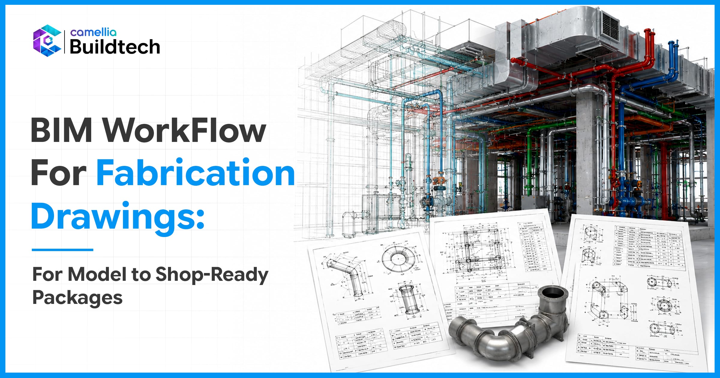
Let’s look at MEP ductwork prefabrication example. The workflow starts with a design model in Revit where MEP engineer models the duct routes and equipment. The model is then federated with architectural and structural models in Navisworks to clash coordinate, where conflicts with beams, columns and other services are addressed. The coordinated model is moved to Fabrication CADmep where design geometry is turned into fabrication geometry, seam locations, hanger points and connection details are modeled. Shop drawings and spool drawings are generated straight from the detailed model, where each spool gets its own ID, service code and installation sequence. Finally, isometric drawings and NC data are exported to the cutting machine that cuts the duct sections that are then shipped on site and ready for installation.
Business Case & ROI
The adoption of the integrated BIM-to-fabrication workflow brings clear ROI through reduced rework, material waste, and lead times. Connected workflows save from manual redraws, reduce rework, improve labor forecasting and boost fabrication throughput without hiring more people. Contractors who use connected BIM workflows save up to 74 percent of spooling time, get 40 percent fabrication throughput increase and reduce rework through model-to-field accuracy. Prefabrication with the help of BIM can save 30 percent or more labor hours by moving construction labor from uncontrolled jobsite environment to controlled fabrication environment.
Measure your ROI through these simple KPIs:
- The percent of RFI reduction (typically, 25 percent or more)
- Turnaround time for shop drawings (benchmark yourself against the baseline)
- Material waste reduction (industry reports point at 20 percent of reduction)
- Prefabrication yield and shop throughput
- Laborhours for field installation (industry case studies show 40 percent lowerlabor hours for field installation)
Implementation Roadmap
Phase 1: Pilot – Choose a small project/system (stairs, duct spools, pipe racks) for a test case. Define a project-specific BEP with clear LOD and fabrication requirements. Choose your toolset and cross-functional train design, coordination and fabrication teams. Set up your CDE and version control practices prior to modeling.
Phase 2: Scale – Standardize your templates for fabrication families and attribute schema. Automate validation and QA/QC workflows. Integrate NC and CAM exports into production pipeline. Build up library of fabrication-ready families and connection details that can be used in multiple projects. Document lessons learned during the pilot and refine your standards.
Phase 3: Continuous improvement – Systematically collect feedback from the field and feed as-built data back to the model. Benchmark your KPIs against project baselines and improve your rules and templates. Expand your workflow to multiple disciplines and projects. Use the data from the finished projects to improve estimating, sequencing and prefabrication planning for upcoming projects.
Frequently Asked Questions
What is included in fabrication drawings services and how does BIM improves them?
Fabrication drawings services include shop drawings, material list, cutting and assembly details, spool drawings, and NC or CAM exports. BIM improves them by automating BOM extraction, removing errors from manual redraws, and assuring that every drawing is generated from a coordinated and clash-free model.
What LOD in BIM is required for fabrication-ready models?
The fabrication-ready models typically require LOD 350-LOD 400. LOD 350 includes connections and interfaces between building elements for detailed coordination. LOD 400 includes fabrication-level detail with precise dimensions and assembly information for shop drawings, prefabrication and installation sequencing. Exact requirements might differ by discipline and by the project contract, but these targets should be defined in BEP.
What file formats should I ask from my BIM or Fabrication team?
Request native model files (RVT for Revit, Tekla for structural steel) for internal use, IFC for model exchange and interoperability, DWG and DXF for drawings delivery, and NC or CAM exports for production machinery. In addition to these files, request BOM exports in structured format such as CSV.
How long does it take to generate shop drawings from a coordinated BIM model?
It depends on the discipline and complexity of the project. Small systems such as duct spools or pipe racks can generate shop drawings in days from a coordinated model. Larger structural steel packages may take several weeks. Coordinated model eliminates most of the reinterpretation and redrawing from traditional workflows and compresses the process dramatically.
How do you validate fabrication drawings before production?
Validation is done through a combination of automated and manual validations. Automated clash detection and attribute validation assure the model completeness. Manual detailer review validates constructability. BOM and cutting lists reconciliation is performed. Factory test cut, sample, or first off approval is produced before production start.
How much cost/time saving can we get by moving to BIM-driven fabrication drawings services?
On the typical projects you can expect rework and faster installation, and therefore cost reductions. According to industry statistics, the BIM adoption saves on average 20 percent of project timelines, 15 percent of costs, 30 percent of design errors and 25 percent of RFIs. The connected BIM workflows demonstrated up to 74 percent of spooling time reduction and 40 percent of fabrication throughput increase. Actual savings would be based on the scale of the project and completeness of your implementation.
Ready to revolutionize your fabrication drawings workflow with BIM? Camellia Buildtech provides end-to-end BIM fabrication drawings services-from coordinated design models to shop-ready packages with NC exports. Our team helps fabricators and contractors reduce lead times, eliminate rework and improve their bottom line through connected BIM workflows. Contact us to learn more about your next project.